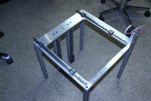
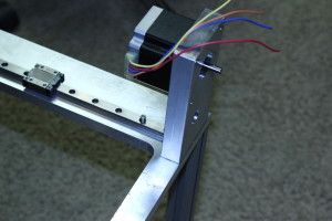
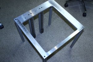
I decided that a 3D printer would really help me prototype parts faster and make it easier (and cheaper) to make electronics enclosures. I wasn’t impressed with most of the sub-$2000 models and I didn’t have the $50k to drop on a professional model so I decided to build instead of buy. I started with a heavy, but very sturdy, aluminum frame.
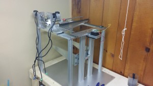
The X/Y axis use servo motors and the Z axis uses a simple stepper motor. Servo motors are much faster, quieter and more importantly they are much more accurate. I needed these qualities in the axis that would be doing the majority of the motion. The Z axis won’t be moving near as much so there is less of a chance of lost steps. I decided on anti-backlash acme screws for the motion method. Most hobby level printers use urethane timing belts which are much cheaper but also less accurate, wear out faster, and require regular adjustment. These screws will last the life of the machine.
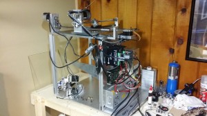
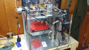
More parts are now attached. The servo and stepper drives are installed as well as some of the power supplies.

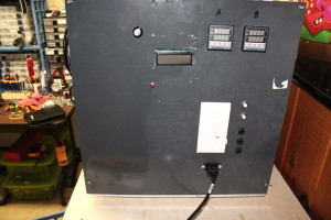
Drives wired up and control panel fitted with breakers and the PID temperature controllers for the extruder nozzles.
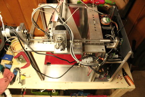
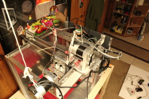
I opted for a gantry system for the X/Y axis. The only direction the part moves is in the Z axis which means there is no chance of the part tipping over. cheaper printers have the table move but they have to run slower because rapid movements can shake a part lose from the table or cause deformation.
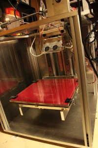
Here is a shot of the heated bed (12″x12″) and the extruder bodies. 2 fans sit in front of the extruder so cool the part as it’s being made. The heated bed allows me to run ABS plastic in addition to PLA. The heat keeps the part pliable while it’s being made.
